Control Light Using JAVA and Arduino Programing
You can communicate with and control an Arduino from Java running on another computer.
Java Code:
package Kittu;
import arduino.*;
import javax.swing.JOptionPane;
public class NewJFrame extends javax.swing.JFrame {
Arduino aa=new Arduino();
public NewJFrame() {
super("Home Automation");
initComponents();
aa.setPortDescription("COM8");
aa.openConnection();
Message.setText("Light is Off");
}
@SuppressWarnings("unchecked")
// <editor-fold defaultstate="collapsed" desc="Generated Code">
private void initComponents() {
Btn1 = new javax.swing.JButton();
Message = new javax.swing.JLabel();
setDefaultCloseOperation(javax.swing.WindowConstants.EXIT_ON_CLOSE);
Btn1.setFont(new java.awt.Font("Times New Roman", 0, 18)); // NOI18N
Btn1.setIcon(new javax.swing.ImageIcon(getClass().getResource("/Kittu/image/LightOff.jpg"))); // NOI18N
Btn1.addMouseListener(new java.awt.event.MouseAdapter() {
public void mouseClicked(java.awt.event.MouseEvent evt) {
Btn1MouseClicked(evt);
}
});
Message.setFont(new java.awt.Font("Times New Roman", 0, 14)); // NOI18N
Message.setHorizontalAlignment(javax.swing.SwingConstants.CENTER);
javax.swing.GroupLayout layout = new javax.swing.GroupLayout(getContentPane());
getContentPane().setLayout(layout);
layout.setHorizontalGroup(
layout.createParallelGroup(javax.swing.GroupLayout.Alignment.LEADING)
.addGroup(layout.createSequentialGroup()
.addGap(200, 200, 200)
.addGroup(layout.createParallelGroup(javax.swing.GroupLayout.Alignment.LEADING, false)
.addComponent(Btn1, javax.swing.GroupLayout.PREFERRED_SIZE, 108, javax.swing.GroupLayout.PREFERRED_SIZE)
.addComponent(Message, javax.swing.GroupLayout.DEFAULT_SIZE, javax.swing.GroupLayout.DEFAULT_SIZE, Short.MAX_VALUE))
.addContainerGap(209, Short.MAX_VALUE))
);
layout.setVerticalGroup(
layout.createParallelGroup(javax.swing.GroupLayout.Alignment.LEADING)
.addGroup(layout.createSequentialGroup()
.addGap(51, 51, 51)
.addComponent(Message, javax.swing.GroupLayout.PREFERRED_SIZE, 23, javax.swing.GroupLayout.PREFERRED_SIZE)
.addPreferredGap(javax.swing.LayoutStyle.ComponentPlacement.RELATED)
.addComponent(Btn1)
.addContainerGap(111, Short.MAX_VALUE))
);
pack();
setLocationRelativeTo(null);
}// </editor-fold>
private void Btn1MouseClicked(java.awt.event.MouseEvent evt) {
try{
String a="1";//1 for on Light
String b="2";//2 for off light
if(Message.getText().equals("Light is Off"))
{
aa.serialWrite(a);
Message.setText("Light is On");
Btn1.setIcon(new javax.swing.ImageIcon(getClass().getResource("/Kittu/image/LightOn.jpg")));
}
else{
aa.serialWrite(b);
Message.setText("Light is Off");
Btn1.setIcon(new javax.swing.ImageIcon(getClass().getResource("/Kittu/image/LightOff.jpg")));
}
}catch(Exception e)
{
JOptionPane.showMessageDialog(null,e);
}
}
public static void main(String args[]) {
/* Set the Nimbus look and feel */
//<editor-fold defaultstate="collapsed" desc=" Look and feel setting code (optional) ">
/* If Nimbus (introduced in Java SE 6) is not available, stay with the default look and feel.
* For details see http://download.oracle.com/javase/tutorial/uiswing/lookandfeel/plaf.html
*/
try {
for (javax.swing.UIManager.LookAndFeelInfo info : javax.swing.UIManager.getInstalledLookAndFeels()) {
if ("Nimbus".equals(info.getName())) {
javax.swing.UIManager.setLookAndFeel("com.jtattoo.plaf.acryl.AcrylLookAndFeel");
break;
}
}
} catch (ClassNotFoundException ex) {
java.util.logging.Logger.getLogger(NewJFrame.class.getName()).log(java.util.logging.Level.SEVERE, null, ex);
} catch (InstantiationException ex) {
java.util.logging.Logger.getLogger(NewJFrame.class.getName()).log(java.util.logging.Level.SEVERE, null, ex);
} catch (IllegalAccessException ex) {
java.util.logging.Logger.getLogger(NewJFrame.class.getName()).log(java.util.logging.Level.SEVERE, null, ex);
} catch (javax.swing.UnsupportedLookAndFeelException ex) {
java.util.logging.Logger.getLogger(NewJFrame.class.getName()).log(java.util.logging.Level.SEVERE, null, ex);
}
//</editor-fold>
/* Create and display the form */
java.awt.EventQueue.invokeLater(new Runnable() {
public void run() {
new NewJFrame().setVisible(true);
}
});
}
// Variables declaration - do not modify
private javax.swing.JButton Btn1;
private javax.swing.JLabel Message;
// End of variables declaration
}
Arduino Code:
void setup() {
pinMode(8,OUTPUT);
Serial.begin(9600);
}
void loop() {
if(Serial.available()>0)
{
int data=Serial.parseInt();
if(data==1)
{
digitalWrite(8,HIGH);
}
if(data==2){
digitalWrite(8,LOW);
}
}
}
Download Arduino Code
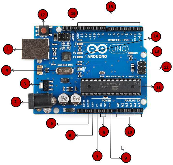
Arduino Board

What is Arduino?
Arduino is an open-source electronics platform based on easy-to-use hardware and software. Arduino boards are able to read inputs - light on a sensor, a finger on a button, or a Twitter message - and turn it into an output - activating a motor, turning on an LED, publishing something online. You can tell your board what to do by sending a set of instructions to the microcontroller on the board. To do so you use the Arduino programming language (based on Wiring), and the Arduino Software (IDE), based on Processing.
Over the years Arduino has been the brain of thousands of projects, from everyday objects to complex scientific instruments. A worldwide community of makers - students, hobbyists, artists, programmers, and professionals - has gathered around this open-source platform, their contributions have added up to an incredible amount of accessible knowledge that can be of great help to novices and experts alike.
Arduino was born at the Ivrea Interaction Design Institute as an easy tool for fast prototyping, aimed at students without a background in electronics and programming. As soon as it reached a wider community, the Arduino board started changing to adapt to new needs and challenges, differentiating its offer from simple 8-bit boards to products for IoT applications, wearable, 3D printing, and embedded environments. All Arduino boards are completely open-source, empowering users to build them independently and eventually adapt them to their particular needs. The software, too, is open-source, and it is growing through the contributions of users worldwide.
 |
Power USB
Arduino board can be powered by using the USB cable from your computer. All you need to do is connect the USB cable to the USB connection (1).
|
 |
Power (Barrel Jack)
Arduino boards can be powered directly from the AC mains power supply by connecting it to the Barrel Jack (2).
|
 |
Voltage Regulator
The function of the voltage regulator is to control the voltage given to the Arduino board and stabilize the DC voltages used by the processor and other elements.
|
 |
Crystal Oscillator
The crystal oscillator helps Arduino in dealing with time issues. How does Arduino calculate time? The answer is, by using the crystal oscillator. The number printed on top of the Arduino crystal is 16.000H9H. It tells us that the frequency is 16,000,000 Hertz or 16 MHz.
|
 |
Arduino Reset
You can reset your Arduino board, i.e., start your program from the beginning. You can reset the UNO board in two ways. First, by using the reset button (17) on the board. Second, you can connect an external reset button to the Arduino pin labelled RESET (5).
|
 |
Pins (3.3, 5, GND, Vin)
|
 |
Analog pins
The Arduino UNO board has six analog input pins A0 through A5. These pins can read the signal from an analog sensor like the humidity sensor or temperature sensor and convert it into a digital value that can be read by the microprocessor.
|
 |
Main microcontroller
Each Arduino board has its own microcontroller (11). You can assume it as the brain of your board. The main IC (integrated circuit) on the Arduino is slightly different from board to board. The microcontrollers are usually of the ATMEL Company. You must know what IC your board has before loading up a new program from the Arduino IDE. This information is available on the top of the IC. For more details about the IC construction and functions, you can refer to the data sheet.
|
 |
ICSP pin
Mostly, ICSP (12) is an AVR, a tiny programming header for the Arduino consisting of MOSI, MISO, SCK, RESET, VCC, and GND. It is often referred to as an SPI (Serial Peripheral Interface), which could be considered as an "expansion" of the output. Actually, you are slaving the output device to the master of the SPI bus.
|
 |
Power LED indicator
This LED should light up when you plug your Arduino into a power source to indicate that your board is powered up correctly. If this light does not turn on, then there is something wrong with the connection.
|
 |
TX and RX LEDs
On your board, you will find two labels: TX (transmit) and RX (receive). They appear in two places on the Arduino UNO board. First, at the digital pins 0 and 1, to indicate the pins responsible for serial communication. Second, the TX and RX led (13). The TX led flashes with different speed while sending the serial data. The speed of flashing depends on the baud rate used by the board. RX flashes during the receiving process.
|
 |
Digital I/O
The Arduino UNO board has 14 digital I/O pins (15) (of which 6 provide PWM (Pulse Width Modulation) output. These pins can be configured to work as input digital pins to read logic values (0 or 1) or as digital output pins to drive different modules like LEDs, relays, etc. The pins labeled “~” can be used to generate PWM.
|
 |
AREF
AREF stands for Analog Reference. It is sometimes, used to set an external reference voltage (between 0 and 5 Volts) as the upper limit for the analog input pins.
|
Relay Module

A relay is an electrically operated device. It has a control system and (also called input circuit or input contactor) and controlled system (also called output circuit or output cont actor). It is frequently used in automatic control circuit. To put it simply, it is an automatic switch to controlling a high-current circuit with a low-current signal.
The advantages of a relay lie in its lower inertia of the moving, stability, long-term reliability and small volume. It is widely adopted in devices of power protection, automation technology, sport, remote control, reconnaissance and communication, as well as in devices of electromechanics and power electronics. Generally speaking, a relay contains an induction part which can reflect input variable like current, voltage, power, resistance, frequency, temperature, pressure, speed and light etc. It also contains an actuator module (output) which can energize or de-energize the connection of controlled circuit. There is an intermediary part between input part and output part that is used to coupling and isolate input current, as well as actuate the output. When the rated value of input (voltage, current and temperature etc.) is above the critical value, the controlled output circuit of relay will be energized or de-energized.
NB: input into a relay can be divided into two categories: electrical quantities (including current, voltage, frequency, power etc.) and non- electrical quantities(including temperature, pressure, speed, etc.)
1) Good in safety. In power system and high voltage system, the lower current can control the higher one.
2) 1-channel high voltage system output, meeting the needs of single channel control
3) Wide range of controllable voltage.
4) Being able to control high load current, which can reach 240V, 10A
5) With a normally-open (NO) contact and a normally-closed (NC) contacts

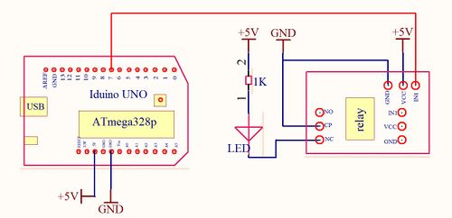
Connection Diagram Arduino and Relay

The advantages of a relay lie in its lower inertia of the moving, stability, long-term reliability and small volume. It is widely adopted in devices of power protection, automation technology, sport, remote control, reconnaissance and communication, as well as in devices of electromechanics and power electronics. Generally speaking, a relay contains an induction part which can reflect input variable like current, voltage, power, resistance, frequency, temperature, pressure, speed and light etc. It also contains an actuator module (output) which can energize or de-energize the connection of controlled circuit. There is an intermediary part between input part and output part that is used to coupling and isolate input current, as well as actuate the output. When the rated value of input (voltage, current and temperature etc.) is above the critical value, the controlled output circuit of relay will be energized or de-energized.
NB: input into a relay can be divided into two categories: electrical quantities (including current, voltage, frequency, power etc.) and non- electrical quantities(including temperature, pressure, speed, etc.)
Features
The features of 1-Channel Relay module are as follow:1) Good in safety. In power system and high voltage system, the lower current can control the higher one.
2) 1-channel high voltage system output, meeting the needs of single channel control
3) Wide range of controllable voltage.
4) Being able to control high load current, which can reach 240V, 10A
5) With a normally-open (NO) contact and a normally-closed (NC) contacts
Overview and Hardware Resources
Development Environment Setting
Interface Connecting and Setting


Connection Diagram Arduino and Relay

Comments
Post a Comment